A pressure reading is only useful when it remains dependable in the conditions where it is taken. A Thin-Film Pressure Sensor can suit compact equipment that needs a stable signal, robust construction, and practical integration. Its sensing element typically uses a thin resistive film deposited on a deformable surface. When pressure bends that surface, the electrical resistance changes and can be measured as an output signal.
Small details matter. Temperature shifts, vibration, pressure spikes, and the measured medium can all affect performance. A sensor that works well on a clean laboratory bench may behave differently inside a hot pump housing or a vibrating machine. Thin-film construction can support compact designs, but it does not remove the need for careful calibration, suitable materials, and sound installation. Not always.
Choosing a sensor means matching its specifications to the application, rather than relying on a single headline rating. Check the operating range, accuracy, temperature limits, response needs, electrical interface, and process connection. Ask how the sensor performs over time, and whether its packaging suits the fluid or gas being measured. These checks help engineers compare options on evidence instead of assumptions.
There is no universal best choice. That deserves a second look. A Thin-Film Pressure Sensor may be a strong option where size and durability matter, yet another sensing technology may fit better when cost, extreme conditions, or serviceability dominate. The right decision comes from testing the actual operating environment and reviewing the manufacturer’s documented data.
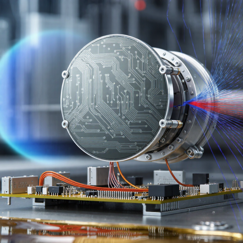
A thin film pressure sensor measures pressure by detecting tiny changes in a metal film bonded to a diaphragm. The film is deposited in a very thin layer, often using a vacuum process. When pressure flexes the diaphragm, the film stretches or compresses, changing its electrical resistance. A circuit converts that change into a usable pressure reading. The sensing element is compact, with no bulky foil gauge attached to the diaphragm.
This design can offer good repeatability, stability, and resistance to vibration, depending on materials and construction. It suits equipment where space is limited or pressure readings must remain consistent over many cycles. But “thin film” alone does not guarantee accuracy. Temperature, pressure range, mounting stress, and calibration all affect performance. No sensor is perfect. A detail easy to overlook is the process connection: poor installation can distort readings even when the sensing element is well made. Checking the specification against real operating conditions matters more than relying on a label.
Tips: Compare the sensor’s pressure range, temperature limits, and output type with your system. Follow the manufacturer’s calibration guidance, and check whether the reading shifts after installation. Keep a record. A small offset may reveal a mounting issue, not a faulty sensor.

A thin film pressure sensor measures pressure by turning a tiny mechanical movement into an electrical signal. Pressure enters through a port and pushes against a metal diaphragm. The diaphragm bends slightly, often too little to see. Thin resistive elements deposited on its surface stretch or compress with that movement. Their electrical resistance changes as the diaphragm flexes. Small movement, measurable signal.
A circuit detects this resistance shift, commonly through a Wheatstone bridge. The bridge converts it into a voltage that an instrument or controller can read. During calibration, technicians apply known pressures and compare the output with reference readings. This establishes a pressure-to-signal relationship. Temperature, mounting stress, vibration, and pressure beyond the sensor’s range can affect accuracy. Real installations can be messier than bench tests.
Tips: Keep the pressure port clean and use compatible seals. Tighten fittings evenly; uneven mounting can strain the diaphragm before measurement begins. Let the sensor reach a stable temperature before taking critical readings. If the output drifts, check wiring and zero readings before assuming the sensor has failed. Set calibration intervals according to operating conditions.
Thin-film pressure sensors use a deposited sensing layer bonded closely to a metal diaphragm. This construction supports a compact package and helps the sensing element withstand vibration and repeated pressure cycles. The short mechanical path also helps deliver a quick, stable response in hydraulic lines, test rigs, and compact equipment. Small parts matter.
Performance depends on more than sensitivity. Hysteresis, repeatability, temperature effects, and long-term drift all shape useful accuracy. IEC 60770-1 identifies these as key characteristics for evaluating industrial transmitters, so compare them under the same pressure range and test conditions. NIST Special Publication 250-39 documents pressure-calibration capabilities spanning roughly 1 kPa to 280 MPa; that range shows why sensor selection must match the actual operating pressure, not just the nominal accuracy figure. Thin-film designs can offer good stability in demanding environments, but they are not automatically the best choice. Mounting stress, thermal cycling, and poor calibration can still skew readings. Worth checking. A real-world trial under the application’s temperature and vibration conditions is often more revealing than a specification sheet.
Thin-film pressure sensors are used where space is tight and pressure readings need to be captured close to the process. Their compact sensing elements can be integrated into equipment without adding bulky assemblies. That makes them useful across several industries, though performance depends on the design and installation.
In automotive systems, these sensors can monitor oil, fuel, or hydraulic pressure, where vibration and temperature changes are part of daily operation. Industrial equipment uses them in pumps, compressors, and process lines to help operators spot pressure shifts before they affect production.
Small details matter. A poorly placed sensor may read pressure differently from the point that needs monitoring.
In medical and laboratory equipment, thin-film sensors can support pressure measurement in devices such as fluid-handling systems and diagnostic instruments. They are also found in aerospace and energy applications, where low weight and limited installation space can be valuable.
Each setting brings different demands: a sensor exposed to heat, moisture, or repeated pressure cycles may need extra protection and careful calibration.
Fit is not everything. Engineers should check the pressure range, materials, and expected service conditions, since compact size alone does not guarantee reliable readings.
Why Choose a Thin Film Pressure Sensor?
Factors to Consider When Selecting a Thin Film Pressure Sensor
A thin film pressure sensor can suit compact systems that need stable measurements, but selection starts with the operating conditions. Define the normal pressure range, expected peaks, and whether pressure changes slowly or in sharp pulses. The sensor’s range should match the application; an oversized range can make small pressure changes harder to detect. Check which materials contact the measured fluid or gas. Compatibility matters, especially when the medium is hot, corrosive, or prone to leaving residue. Temperature matters too. Compare the sensor’s operating limits with both process temperatures and ambient conditions around the installation. Small details matter.
Next, consider accuracy, repeatability, response time, and the electrical output your control system accepts. A high accuracy figure is not the whole story; mounting stress, vibration, and temperature shifts can affect readings in service. Review overload limits and expected service life, not just the normal operating range. If pressure fluctuates quickly, response time may be more important than a tiny improvement in static accuracy. Check connector style, available space, and how the sensor will be calibrated after installation. In practice, a perfect specification sheet can still meet a messy installation. Leave room for wiring, avoid forcing the port into alignment, and verify readings under real operating conditions.
| Selection Factor | What to Evaluate | Thin-Film Sensor Considerations | Practical Selection Guidance |
|---|---|---|---|
| Sensing principle | Understand how pressure is converted into an electrical signal. | A thin resistive film is deposited on a diaphragm. Pressure-induced diaphragm strain changes resistance, commonly measured with a Wheatstone bridge. | Confirm the sensor’s output type and whether the required signal conditioning is built in or supplied separately. |
| Pressure range | Specify the normal operating range, maximum pressure, and any pressure spikes. | Available ranges depend on diaphragm geometry, materials, and sensor design; there is no single pressure range for all thin-film sensors. | Choose a range that covers normal operation while checking proof and burst pressure ratings separately. |
| Accuracy and stability | Compare total error, repeatability, hysteresis, and long-term drift over the intended conditions. | Performance is design- and calibration-dependent. Deposited gauges can support stable, compact constructions, but thin-film technology alone does not guarantee a particular accuracy. | Review the complete error specification, its units, reference conditions, and calibration interval. |
| Temperature conditions | Check operating and storage temperature, temperature effects on zero and span, and thermal cycling. | The thin-film element may be suitable for rugged designs, but allowable temperature and compensated performance depend on the sensor materials and electronics. | Use the specified compensated range, not just the maximum operating temperature, when estimating measurement error. |
| Media compatibility | Identify the fluid or gas, its chemistry, cleanliness, and possible corrosive or abrasive effects. | Compatibility is determined mainly by wetted materials, seals, and isolation structure—not by the thin-film sensing layer alone. | Verify every wetted material against the process media and check whether a chemical seal or diaphragm is required. |
| Response and vibration | Consider pressure change rate, required bandwidth, mechanical shock, and vibration exposure. | Dynamic response depends on the diaphragm, package, fluid connection, and electronics; the sensing-film type by itself does not determine response time. | Check frequency response or response-time data for the complete assembly and intended installation. |
| Electrical interface | Match supply voltage, output format, wiring, grounding, and controller input requirements. | An unamplified strain-gauge bridge commonly produces a small differential signal; conditioned versions may provide voltage or current outputs. | Confirm whether the output is bridge-level or conditioned and account for cable length and electrical noise. |
| Installation and connection | Check port size, thread standard, mounting orientation, sealing method, and available space. | Thin-film sensing elements can be integrated into different packages, so connector and port options vary by model. | Verify mechanical drawings and sealing requirements before installation; avoid applying unapproved torque to the housing. |
| Calibration and maintenance | Determine calibration needs, inspection access, and the consequences of measurement drift. | Calibration requirements depend on the application, accuracy target, operating environment, and sensor specifications. | Set a verification schedule based on risk and observed performance, and retain calibration records where required. |
Note: Specifications vary by sensor design. Confirm operating limits and performance using the technical documentation for the specific model and application.